
Page 283 - Rock Mechanics For Underground Mining
P. 283
DESIGN PRACTICE IN BLOCKY ROCK
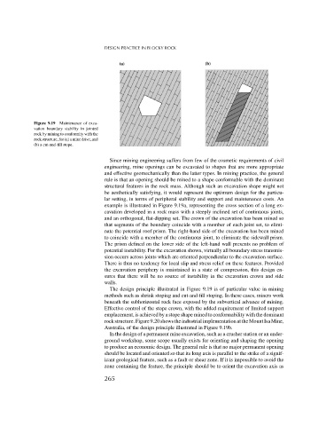
Figure 9.19 Maintenance of exca-
vation boundary stability in jointed
rock by mining to conformity with the
rockstructure, for(a)amine drive,and
(b) a cut-and-fill stope.
Since mining engineering suffers from few of the cosmetic requirements of civil
engineering, mine openings can be excavated to shapes that are more appropriate
and effective geomechanically than the latter types. In mining practice, the general
rule is that an opening should be mined to a shape conformable with the dominant
structural features in the rock mass. Although such an excavation shape might not
be aesthetically satisfying, it would represent the optimum design for the particu-
lar setting, in terms of peripheral stability and support and maintenance costs. An
example is illustrated in Figure 9.19a, representing the cross section of a long ex-
cavation developed in a rock mass with a steeply inclined set of continuous joints,
and an orthogonal, flat-dipping set. The crown of the excavation has been mined so
that segments of the boundary coincide with a member of each joint set, to elimi-
nate the potential roof prism. The right-hand side of the excavation has been mined
to coincide with a member of the continuous joint, to eliminate the sidewall prism.
The prism defined on the lower side of the left-hand wall presents no problem of
potential instability. For the excavation shown, virtually all boundary stress transmis-
sion occurs across joints which are oriented perpendicular to the excavation surface.
There is thus no tendency for local slip and stress relief on these features. Provided
the excavation periphery is maintained in a state of compression, this design en-
sures that there will be no source of instability in the excavation crown and side
walls.
The design principle illustrated in Figure 9.19 is of particular value in mining
methods such as shrink stoping and cut-and-fill stoping. In these cases, miners work
beneath the subhorizontal rock face exposed by the subvertical advance of mining.
Effective control of the stope crown, with the added requirement of limited support
emplacement, is achieved by a stope shape mined to conformability with the dominant
rock structure. Figure 9.20 shows the industrial implementation at the Mount Isa Mine,
Australia, of the design principle illustrated in Figure 9.19b.
In the design of a permanent mine excavation, such as a crusher station or an under-
ground workshop, some scope usually exists for orienting and shaping the opening
to produce an economic design. The general rule is that no major permanent opening
should be located and oriented so that its long axis is parallel to the strike of a signif-
icant geological feature, such as a fault or shear zone. If it is impossible to avoid the
zone containing the feature, the principle should be to orient the excavation axis as
265