
Page 284 - Rock Mechanics For Underground Mining
P. 284
EXCAVATION DESIGN IN BLOCKY ROCK
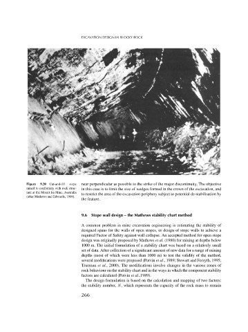
Figure 9.20 Cut-and-fill stope near perpendicular as possible to the strike of the major discontinuity. The objective
mined to conformity with rock struc- in this case is to limit the size of wedges formed in the crown of the excavation, and
ture at the Mount Isa Mine, Australia
to restrict the area of the excavation periphery subject to potential de-stabilisation by
(after Mathews and Edwards, 1969).
the feature.
9.6 Stope wall design – the Mathews stability chart method
A common problem in mine excavation engineering is estimating the stability of
designed spans for the walls of open stopes, or design of stope walls to achieve a
required Factor of Safety against wall collapse. An accepted method for open stope
design was originally proposed by Mathews et al. (1980) for mining at depths below
1000 m. The initial formulation of a stability chart was based on a relatively small
set of data. After collection of a significant amount of new data for a range of mining
depths (most of which were less than 1000 m) to test the validity of the method,
several modifications were proposed (Potvin et al., 1989; Stewart and Forsyth, 1995;
Trueman et al., 2000). The modifications involve changes in the various zones of
rock behaviour on the stability chart and in the ways in which the component stability
factors are calculated (Potvin et al.,1989).
The design formulation is based on the calculation and mapping of two factors:
the stability number, N, which represents the capacity of the rock mass to remain
266