
Page 269 - Rock Mechanics For Underground Mining
P. 269
IDENTIFICATION OF POTENTIAL BLOCK FAILURE MODES – BLOCK THEORY
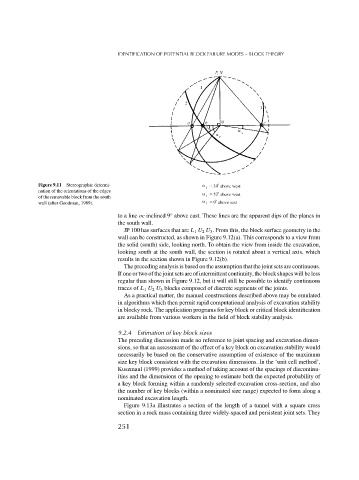
Figure 9.11 Stereographic determi-
nation of the orientations of the edges
of the removable block from the south
wall (after Goodman, 1989).
◦
to a line oc inclined 9 above east. These lines are the apparent dips of the planes in
the south wall.
JP 100 has surfaces that are L 1 U 2 U 3 . From this, the block surface geometry in the
wall can be constructed, as shown in Figure 9.12(a). This corresponds to a view from
the solid (south) side, looking north. To obtain the view from inside the excavation,
looking south at the south wall, the section is rotated about a vertical axis, which
results in the section shown in Figure 9.12(b).
The preceding analysis is based on the assumption that the joint sets are continuous.
If one or two of the joint sets are of intermittent continuity, the block shapes will be less
regular than shown in Figure 9.12, but it will still be possible to identify continuous
traces of L 1 U 2 U 3 blocks composed of discrete segments of the joints.
As a practical matter, the manual constructions described above may be emulated
in algorithms which then permit rapid computational analysis of excavation stability
in blocky rock. The application programs for key block or critical block identification
are available from various workers in the field of block stability analysis.
9.2.4 Estimation of key block sizes
The preceding discussion made no reference to joint spacing and excavation dimen-
sions, so that an assessment of the effect of a key block on excavation stability would
necessarily be based on the conservative assumption of existence of the maximum
size key block consistent with the excavation dimensions. In the ‘unit cell method’,
Kuszmaul (1999) provides a method of taking account of the spacings of discontinu-
ities and the dimensions of the opening to estimate both the expected probability of
a key block forming within a randomly selected excavation cross-section, and also
the number of key blocks (within a nominated size range) expected to form along a
nominated excavation length.
Figure 9.13a illustrates a section of the length of a tunnel with a square cross
section in a rock mass containing three widely-spaced and persistent joint sets. They
251