
Page 355 - Rock Mechanics For Underground Mining
P. 355
SUPPORT AND REINFORCEMENT DESIGN
In the finite difference analysis, incremental forms of equation 11.21 are used
in successive computation cycles to calculate incremental nodal displacements, from
which the new configuration of an element can be determined. The axial component of
relative displacement at a node can then be calculated from the absolute displacement
of a node and the absolute displacement of the adjacent rock. The axial force is
obtainedfromequation11.17andtheactivelengthadjacenttothenode,takingaccount
p p
of the limiting condition defined by equation 11.19. The force F x , F y mobilised at
the grout–rock interface at a node is distributed to the zone corners using the natural
co-ordinates of the node as the weight factor; i.e.
p p
F = i F (11.22)
xi x
p
where F are forces assigned to the zone corner.
xi
This formulation of reinforcement mechanics may be readily incorporated in a dy-
namic relaxation, finite difference method of analysis of a deformable medium, such
as the code called FLAC described by Cundall and Board (1988). The solution of a
simple problem involving long, grouted, untensioned cable bolts illustrates applica-
tion of the method of analysis. The problem involves a circular hole of 1 m radius,
excavated in a medium subject to a hydrostatic stress field, of magnitude 10 MPa.
For the elasto–plastic rock mass, the shear and bulk elastic moduli were 4 GPa and
6.7 GPa respectively, and Mohr–Coulomb plasticity was defined by a cohesion of
0.5 MPa, angle of friction of 30 , and dilation angle of 15 . Reinforcement consisted
◦
◦
of a series of radially oriented steel cables, of 15 mm diameter, grouted into 50 mm
diameter holes. The steel had a Young’s modulus of 200 GPa, and a yield load of
−1
1 GN. Values assigned to K bond and S bond were 45 GN m −2 and 94 kN m . These
properties correspond to a grout with a Young’s modulus of 21.5 GPa and a peak bond
strength ( peak )of2MPa.
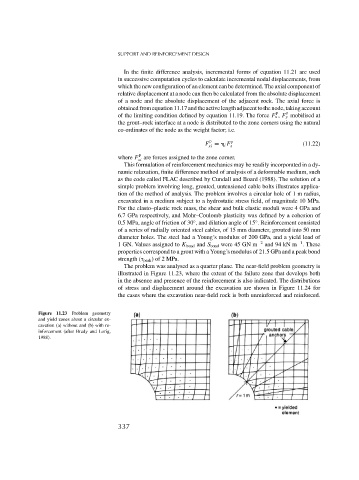
The problem was analysed as a quarter plane. The near-field problem geometry is
illustrated in Figure 11.23, where the extent of the failure zone that develops both
in the absence and presence of the reinforcement is also indicated. The distributions
of stress and displacement around the excavation are shown in Figure 11.24 for
the cases where the excavation near-field rock is both unreinforced and reinforced.
Figure 11.23 Problem geometry
and yield zones about a circular ex-
cavation (a) without and (b) with re-
inforcement (after Brady and Lorig,
1988).
337