
Page 350 - Rock Mechanics For Underground Mining
P. 350
ROCK SUPPORT AND REINFORCEMENT
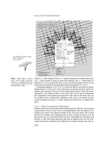
Figure 11.18 Typical working where b = yield strength of bolt, c = uniaxial compressive strength of the rock,
sketch used during preliminary peak = shear strength of grout or grout–rock interface, and L = bond length. In
layout of a rockbolting pattern for equation 11.15, it is assumed that shear occurs at the hole boundary. If shear occurs
an excavation in jointed rock (after
Hoek and Brown, 1980). at the bolt–grout interface, the appropriate diameter in equation 11.15 is d 1 .
Considering equations 11.10–11.15, it is observed that any increment of relative
displacement at a joint can be used to determine incremental and then total forces
parallel and transverse to the axis of the reinforcement element. From the known
orientation of the element relative to the joint, these forces can be transformed
into components acting normal and transverse to the joint. In this form, they can
be introduced into a suitable finite difference code, such as the distinct element
scheme described in section 6.7, which simulates the behaviour of a jointed rock
mass.
11.5.3 General or systematic reinforcement
Whereas in the case of local support and reinforcement, the objective was to support
a given block or zone of rock on the excavation periphery, here the objective is to
mobilise and conserve the inherent strength of the rock mass itself. This is often
achieved by creating a self-supporting arch of rock as shown in Figure 11.18. In
the general case, it is expected that the rock mass surrounding the excavation will
fracture or yield. The design approaches that may be applied in this case are rock-
support interaction calculations, the application of empirical design rules, the use
332