
Page 348 - Rock Mechanics For Underground Mining
P. 348
ROCK SUPPORT AND REINFORCEMENT
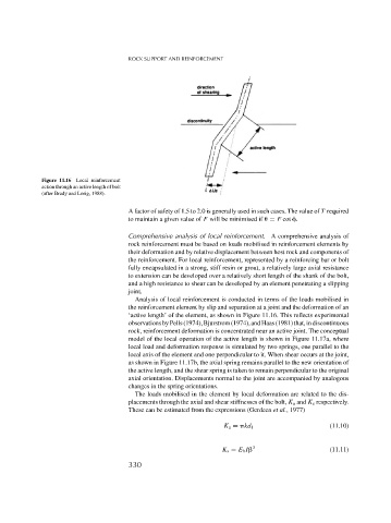
Figure 11.16 Local reinforcement
action through an active length of bolt
(after Brady and Lorig, 1988).
A factor of safety of 1.5 to 2.0 is generally used in such cases. The value of T required
to maintain a given value of F will be minimised if
= F cot .
Comprehensive analysis of local reinforcement. A comprehensive analysis of
rock reinforcement must be based on loads mobilised in reinforcement elements by
their deformation and by relative displacement between host rock and components of
the reinforcement. For local reinforcement, represented by a reinforcing bar or bolt
fully encapsulated in a strong, stiff resin or grout, a relatively large axial resistance
to extension can be developed over a relatively short length of the shank of the bolt,
and a high resistance to shear can be developed by an element penetrating a slipping
joint.
Analysis of local reinforcement is conducted in terms of the loads mobilised in
the reinforcement element by slip and separation at a joint and the deformation of an
‘active length’ of the element, as shown in Figure 11.16. This reflects experimental
observationsbyPells(1974),Bjurstrom(1974),andHaas(1981)that,indiscontinuous
rock, reinforcement deformation is concentrated near an active joint. The conceptual
model of the local operation of the active length is shown in Figure 11.17a, where
local load and deformation response is simulated by two springs, one parallel to the
local axis of the element and one perpendicular to it. When shear occurs at the joint,
as shown in Figure 11.17b, the axial spring remains parallel to the new orientation of
the active length, and the shear spring is taken to remain perpendicular to the original
axial orientation. Displacements normal to the joint are accompanied by analogous
changes in the spring orientations.
The loads mobilised in the element by local deformation are related to the dis-
placements through the axial and shear stiffnesses of the bolt, K a and K s respectively.
These can be estimated from the expressions (Gerdeen et al., 1977)
K a = kd 1 (11.10)
K s = E b I 3 (11.11)
330