
Page 349 - Rock Mechanics For Underground Mining
P. 349
SUPPORT AND REINFORCEMENT DESIGN
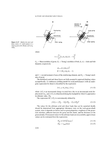
Figure 11.17 Models for axial and
shear action of reinforcement at a
slipping joint (after Brady and Lorig,
1988).
where
1
1 2
k = G g E b /(d 2 /d 1 − 1)
2
G g = Shear modulus of grout, E b = Young’s modulus of bolt, d 2 , d 1 = hole and bolt
diameter, respectively
1
= K/(4E b I) 2
K = 2E g /(d 2 /d 1 − 1)
and I = second moment of area of the reinforcing element, and E g = Young’s mod-
ulus of grout.
The mobilised axial and shear forces are both assumed to approach limiting values
asymptotically. A continuous-yielding model for axial performance (with an analo-
gous expression for shear) is described by the expression
F a = K a | u a | f (F a ) (11.12)
where F a is an incremental change in axial force due to an incremental axial dis-
placement u a , and f (F a ) is a function defining the load path by which F a approaches
a
its ultimate value, P .
ult
The expression for f (F a ) is conveninently defined by
a a a 2
f (F a ) = P − F a (P − F a )/(P ) (11.13)
ult
ult
ult
The values for the ultimate axial and shear loads that can be sustained ideally
should be determined from appropriate laboratory tests on the rock–grout–shank
system, since it depends on factors such as grout properties, roughness of the grout–
rock interface, adhesion between the grout and the shank, and the thickness of the
grout annulus. If measured values for the ultimate loads are not available, approximate
values can be estimated from the expressions
2
P s = 0.67d ( b c ) 2 1 (11.14)
ult 1
P a = peak d 2 L (11.15)
ult
331