
Page 347 - Rock Mechanics For Underground Mining
P. 347
SUPPORT AND REINFORCEMENT DESIGN
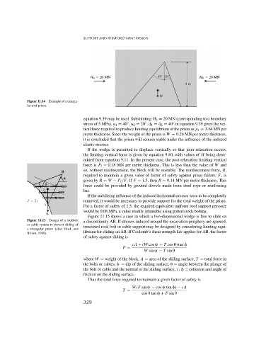
Figure 11.14 Example of a triangu-
lar roof prism.
equation 9.39 may be used. Substituting H 0 = 20 MN (corresponding to a boundary
stress of 5 MPa), 1 = 40 , 2 = 20 , 1 = 2 = 40 in equation 9.39 gives the ver-
◦
◦
◦
tical force required to produce limiting equilibrium of the prism as p = 3.64 MN per
metre thickness. Since the weight of the prism is W = 0.26 MN per metre thickness,
it is concluded that the prism will remain stable under the influence of the induced
elastic stresses.
If the wedge is permitted to displace vertically so that joint relaxation occurs,
the limiting vertical force is given by equation 9.40, with values of H being deter-
mined from equation 9.11. In the present case, the post-relaxation limiting vertical
force is P = 0.18 MN per metre thickness. This is less than the value of W and
so, without reinforcement, the block will be unstable. The reinforcement force, R,
required to maintain a given value of factor of safety against prism failure, F,is
given by R = W − P /F.If F = 1.5, then R = 0.14 MN per metre thickness. This
force could be provided by grouted dowels made from steel rope or reinforcing
bar.
If the stabilising influence of the induced horizontal stresses were to be completely
removed, it would be necessary to provide support for the total weight of the prism.
For a factor of safety of 1.5, the required equivalent uniform roof support pressure
would be 0.08 MPa, a value readily attainable using pattern rock bolting.
Figure 11.15 shows a case in which a two-dimensional wedge is free to slide on
Figure 11.15 Design of a rockbolt a discontinuity AB. If stresses induced around the excavation periphery are ignored,
or cable system to prevent sliding of tensioned rock bolt or cable support may be designed by considering limiting equi-
a triangular prism (after Hoek and
Brown, 1980). librium for sliding on AB. If Coulomb’s shear strength law applies for AB, the factor
of safety against sliding is
cA + (W cos + T cos
) tan
F =
W sin − T sin
where W = weight of the block, A = area of the sliding surface, T = total force in
the bolts or cables, = dip of the sliding surface,
= angle between the plunge of
the bolt or cable and the normal to the sliding surface, c, = cohesion and angle of
friction on the sliding surface.
Thus the total force required to maintain a given factor of safety is
W(F sin − cos tan ) − cA
T =
cos
tan + F sin
329