
Page 345 - Rock Mechanics For Underground Mining
P. 345
SUPPORT AND REINFORCEMENT DESIGN
local support and reinforcement to support individual blocks or loosened zones
on an excavation boundary;
general or systematic reinforcement in which the objective is to mobilise and
conserve the inherent strength of the rock mass; and
support and reinforcement system designed to resist the dynamic loading associ-
ated with rock burst conditions.
Static design analyses for the first two applications will be discussed here. The more
complex case of dynamic or rockburst loading will be considered in section 15.2.3.
11.5.2 Local support and reinforcement
Two types of design analysis will be presented here. The first type involves simple
static limiting equilibrium analyses which essentially treat the system components
as rigid bodies and use simplified models of system mechanics. The second type are
more rigorous and comprehensive analyses which take into account the deformation
and slip or yield of the support and reinforcing system elements and the rock mass.
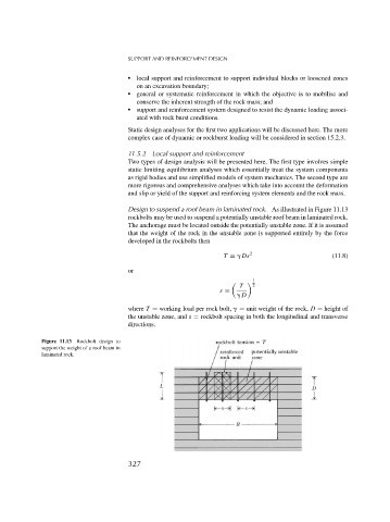
Design to suspend a roof beam in laminated rock. As illustrated in Figure 11.13
rockbolts may be used to suspend a potentially unstable roof beam in laminated rock.
The anchorage must be located outside the potentially unstable zone. If it is assumed
that the weight of the rock in the unstable zone is supported entirely by the force
developed in the rockbolts then
T = Ds 2 (11.8)
or
1
T 2
s =
D
where T = working load per rock bolt, = unit weight of the rock, D = height of
the unstable zone, and s = rockbolt spacing in both the longitudinal and transverse
directions.
Figure 11.13 Rockbolt design to
support the weight of a roof beam in
laminated rock.
327