
Page 377 - Rock Mechanics For Underground Mining
P. 377
UNDERGROUND MINING METHODS
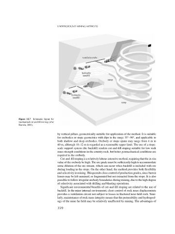
Figure 12.7 Schematic layout for
mechanised cut-and-fill mining (after
Hamrin, 2001).
by vertical pillars, geometrically suitable for application of the method. It is suitable
◦
◦
for orebodies or stope geometries with dips in the range 35 –90 , and applicable to
both shallow and deep orebodies. Orebody or stope spans may range from4mto
40 m, although 10–12 m is regarded as a reasonable upper limit. The use of a stope-
scale support system (the backfill) renders cut-and-fill stoping suitable for low rock
mass strength conditions in the country rock, but better geomechanical conditions are
required in the orebody.
Cut-and-fill stoping is a relatively labour-intensive method, requiring that the in situ
value of the orebody be high. The ore grade must be sufficiently high to accommodate
some dilution of the ore stream, which can occur when backfill is included with ore
during loading in the stope. On the other hand, the method provides both flexibility
and selectivity in mining. This permits close control of production grades, since barren
lenses may be left unmined, or fragmented but not extracted from the stope. It is also
possible to follow irregular orebody boundaries during mining, due to the high degree
of selectivity associated with drilling and blasting operations.
Significant environmental benefits of cut-and-fill stoping are related to the use of
backfill. In the mine internal environment, close control of rock mass displacements
provides a ventilation circuit not subject to losses in fractured near-field rock. Simi-
larly, maintenance of rock mass integrity means that the permeability and hydrogeol-
ogy of the mine far field may be relatively unaffected by mining. The advantages of
359