
Page 435 - Rock Mechanics For Underground Mining
P. 435
DESIGN OF MINE BACKFILL
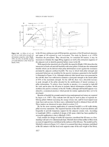
Figure 14.4 (a) Effect of soft and in the fill mass, taking account of fill properties, geometry of the fill and rock structure,
stiff fills on model pillar strength and and spans of fill exposed by rock excavation. The study by Barrett et al. (1978)
deformation properties (after Blight, illustrates the procedures. They showed that, for cemented fill masses, it may be
1984); (b) effect of soft fills on pillar necessary to simulate the stope filling sequence as well as the extraction sequence of
post-peak behaviour (after Swan and
Board, 1989). the adjacent rock to identify potential failure zones in the fill.
Withregardtothestructuralroleofbackfill,thereportbyBlight(1984)describesthe
interaction of both soft and stiff backfills with mine pillars. It indicates the substantial
benefits which can be derived when pillar deformation occurs against the resistance
provided by adjacent confined backfill. The way in which both pillar strength and
post-peak behaviour are modified by the passive resistance generated in the backfill
is illustrated in Figure 14.4a. Although relatively little lateral stress was generated in
the soft fill, there was sufficient to maintain a post-peak strength in the model pillar
of 85% of the maximum strength. For the stiff fill, there was a threefold increase
in peak strength of the pillar attended by the mobilisation of lateral resistance to
pillar deformation. To achieve these benefits in practice, it is essential to tight-fill
the void, and to place the fill prior to inelastic lateral deformation of pillars, which
mobilises the passive resistance of the fill. Further, although stiff backfill appears very
attractive, economical practices which permit its routine application have yet to be
developed.
Benefits of backfill for ground control in deep underground reef mines are reported
by Jager et al. (1987). They indicate how fill may be used in place of regional sta-
bilising pillars without increasing the energy release rate, and for local support near
stope faces and accesses. In these cases, substantial benefit is obtained from soft fill.
These matters are discussed in more detail in section 15.2.
By far the most common application of cemented backfill is as fill walls during
pillar recovery operations. The required function of the fill is to prevent dilution and
frequently to provide temporary support for the adjacent country rock. According
to Landriault (2001), a method of design of fill spans which has been qualified by
successful application is due to Mitchell (1983).
Early models for design of stable fill exposures considered the fill mass as a free-
standing wall and a two-dimensional slope. Mitchell showed that neither of these took
account of support forces mobilised at the surfaces of the fill mass. The model used by
Mitchell is shown in Figure 14.5, where it is assumed that shear resistance mobilised
at the fill contacts with the local rock supports some of the self-weight of the block,
417