
Page 437 - Rock Mechanics For Underground Mining
P. 437
CUT-AND-FILL STOPING
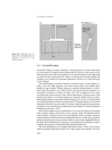
Figure 14.6 Schematic view of a
cut-and-fill stope illustrating the de-
velopment, by mining, of a slot-
shaped excavation.
14.4 Cut-and-fill stoping
Cut-and-fill stoping in narrow orebodies, as described below, has been superseded
to a large degree by longhole bench stoping with fill. However, many aspects of the
following discussion of the rock mechanics of cut-and-fill stoping are also applicable
to multi-lift bench stoping with fill. Further, conventional cut-and-fill stoping will
continue to be of interest for particular applications, because of its high selectivity
and low dilution.
Cut-and-fill stoping is performed mainly in relatively narrow, steeply dipping ore-
bodies, where the stope boundary rock cannot sustain stable, free-standing spans
suitable for open stoping. Whether stoping is overhand (up-dip advance) or under-
hand (down-dip advance), the method involves the incremental development of a
slot-shaped excavation, as shown in Figure 14.6. Fill is emplaced in the mined
excavation after each increment of sub-vertical stope advance. Because miners work
beneath rock surfaces (in overhand stoping) or cemented sandfill masses (in under-
hand stoping) which are regenerated with each mining cycle, the success of the method
is crucially dependent on effective ground control. The geomechanics of cut-and-fill
stoping have therefore been the subject of extensive study. Integration of geomechan-
ics practice in cut-and-fill mining is illustrated in proceedings of a related symposium
(Stephansson and Jones, 1981).
Some useful insights into the geomechanics of cut-and-fill stoping can be gained
from an elastic analysis of the state of stress around a stope. Of particular interest
is the evolution of stresses in the crown and sidewalls of the excavation, during its
vertical extension. Following the ideas established in section 7.6, that any conceivable,
realistic support pressure at an excavation surface can have only a negligible effect on
the elastic stress distribution in a rock mass, it is possible in this exploratory analysis
to neglect the presence of the backfill in the mined and filled zone.
The stress distribution can be readily determined around a series of excavations
with the geometry illustrated in Figure 14.7, using a plane strain analysis. The stope
419