
Page 439 - Rock Mechanics For Underground Mining
P. 439
CUT-AND-FILL STOPING
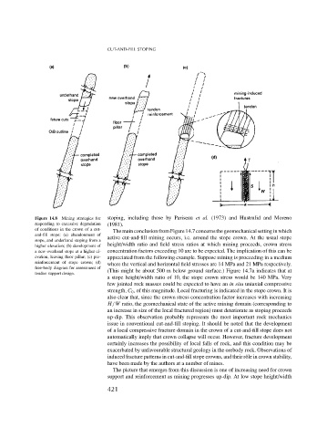
Figure 14.8 Mining strategies for stoping, including those by Pariseau et al. (1973) and Hustrulid and Moreno
responding to excessive degradation (1981).
of conditions in the crown of a cut- The main conclusion from Figure 14.7 concerns the geomechanical setting in which
and-fill stope: (a) abandonment of
stope, and underhand stoping from a active cut-and-fill mining occurs, i.e. around the stope crown. At the usual stope
higher elevation; (b) development of height/width ratio and field stress ratios at which mining proceeds, crown stress
a new overhand stope at a higher el- concentration factors exceeding 10 are to be expected. The implication of this can be
evation, leaving floor pillar; (c) pre- appreciated from the following example. Suppose mining is proceeding in a medium
reinforcement of stope crown; (d) where the vertical and horizontal field stresses are 14 MPa and 21 MPa respectively.
free-body diagram for assessment of
tendon support design. (This might be about 500 m below ground surface.) Figure 14.7a indicates that at
a stope height/width ratio of 10, the stope crown stress would be 140 MPa. Very
few jointed rock masses could be expected to have an in situ uniaxial compressive
strength, C 0 , of this magnitude. Local fracturing is indicated in the stope crown. It is
also clear that, since the crown stress concentration factor increases with increasing
H/W ratio, the geomechanical state of the active mining domain (corresponding to
an increase in size of the local fractured region) must deteriorate as stoping proceeds
up-dip. This observation probably represents the most important rock mechanics
issue in conventional cut-and-fill stoping. It should be noted that the development
of a local compressive fracture domain in the crown of a cut-and-fill stope does not
automatically imply that crown collapse will occur. However, fracture development
certainly increases the possibility of local falls of rock, and this condition may be
exacerbated by unfavourable structural geology in the orebody rock. Observations of
induced fracture patterns in cut-and-fill stope crowns, and their rˆole in crown stability,
have been made by the authors at a number of mines.
The picture that emerges from this discussion is one of increasing need for crown
support and reinforcement as mining progresses up-dip. At low stope height/width
421