
Page 438 - Rock Mechanics For Underground Mining
P. 438
ARTIFICIALLY SUPPORTED MINING METHODS
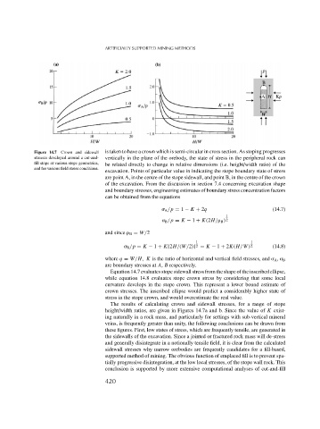
Figure 14.7 Crown and sidewall is taken to have a crown which is semi-circular in cross section. As stoping progresses
stresses developed around a cut-and- vertically in the plane of the orebody, the state of stress in the peripheral rock can
fill stope at various stope geometries, be related directly to change in relative dimensions (i.e. height/width ratio) of the
and for various field stress conditions.
excavation. Points of particular value in indicating the stope boundary state of stress
are point A, in the centre of the stope sidewall, and point B, in the centre of the crown
of the excavation. From the discussion in section 7.4 concerning excavation shape
and boundary stresses, engineering estimates of boundary stress concentration factors
can be obtained from the equations
A /p = 1 − K + 2q (14.7)
1
B /p = K − 1 + K(2H/ B ) 2
and since B = W/2
1 1
B /p = K − 1 + K[2H/(W/2)] 2 = K − 1 + 2K(H/W) 2 (14.8)
where q = W/H, K is the ratio of horizontal and vertical field stresses, and A , B
are boundary stresses at A, B respectively.
Equation 14.7 evaluates stope sidewall stress from the shape of the inscribed ellipse,
while equation 14.8 evaluates stope crown stress by considering that some local
curvature develops in the stope crown. This represent a lower bound estimate of
crown stresses. The inscribed ellipse would predict a considerably higher state of
stress in the stope crown, and would overestimate the real value.
The results of calculating crown and sidewall stresses, for a range of stope
height/width ratios, are given in Figures 14.7a and b. Since the value of K exist-
ing naturally in a rock mass, and particularly for settings with sub-vertical mineral
veins, is frequently greater than unity, the following conclusions can be drawn from
these figures. First, low states of stress, which are frequently tensile, are generated in
the sidewalls of the excavation. Since a jointed or fractured rock mass will de-stress
and generally disintegrate in a notionally tensile field, it is clear from the calculated
sidewall stresses why narrow orebodies are frequently candidates for a fill-based,
supported method of mining. The obvious function of emplaced fill is to prevent spa-
tially progressive disintegration, at the low local stresses, of the stope wall rock. This
conclusion is supported by more extensive computational analyses of cut-and-fill
420