
Page 444 - Rock Mechanics For Underground Mining
P. 444
ARTIFICIALLY SUPPORTED MINING METHODS
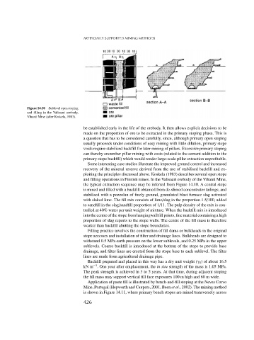
Figure 14.10 Sublevel open stoping
and filling in the Valisaari orebody,
Vihanti Mine (after Koskela, 1983).
be established early in the life of the orebody. It then allows explicit decisions to be
made on the proportion of ore to be extracted in the primary stoping phase. This is
a question that has to be considered carefully, since, although primary open stoping
usually proceeds under conditions of easy mining with little dilution, primary stope
voids require stabilised backfill for later mining of pillars. Excessive primary stoping
can thereby encumber pillar mining with costs (related to the cement addition to the
primary stope backfill) which would render large-scale pillar extraction unprofitable.
Some interesting case studies illustrate the improved ground control and increased
recovery of the mineral reserve derived from the use of stabilised backfill and ex-
ploiting the principles discussed above. Koskela (1983) describes several open stope
and filling operations in Finnish mines. In the Valisaari orebody of the Vihanti Mine,
the typical extraction sequence may be inferred from Figure 14.10. A central stope
is mined and filled with a backfill obtained from de-slimed concentrator tailings, and
stabilised with a pozzolan of finely ground, granulated blast furnace slag activated
with slaked lime. The fill mix consists of lime/slag in the proportion 1.5/100, added
to sandfill in the slag/sandfill proportion of 1/11. The pulp density of the mix is con-
trolled at 40% water per unit weight of mixture. When the backfill mix is introduced
into the centre of the stope from hangingwall fill points, fine material containing a high
proportion of slag reports to the stope walls. The centre of the fill mass is therefore
weaker than backfill abutting the stope boundaries.
Filling practice involves the construction of fill dams or bulkheads in the original
stope accesses and installation of filter and drainage lines. Bulkheads are designed to
withstand 0.5 MPa earth pressure on the lower sublevels, and 0.25 MPa in the upper
sublevels. Coarse backfill is introduced at the bottom of the stope to provide base
drainage, and filter lines are erected from the stope base to each sublevel. The filter
lines are made from agricultural drainage pipe.
Backfill prepared and placed in this way has a dry unit weight ( d ) of about 16.5
−3
kN m . One year after emplacement, the in situ strength of the mass is 1.05 MPa.
The peak strength is achieved in 3 to 5 years. At that time, during adjacent stoping
the fill mass may support vertical fill face exposures 100 m high and 60 m wide.
Application of paste fill is illustrated by bench-and-fill stoping at the Neves Corvo
Mine, Portugal (Hepworth and Caupers, 2001, Been et al., 2002). The mining method
is shown in Figure 14.11, where primary bench stopes are mined transversely across
426