
Page 445 - Rock Mechanics For Underground Mining
P. 445
BACKFILL APPLICATIONS IN OPEN AND BENCH STOPING
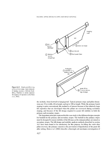
Figure 14.11 Bench-and-fill mining
at Neves Corvo mine: (top) schematic
of mining sequence; (bottom) back-
filling. Numbers in circles represent
the sequence of operations (after Been
et al., 2002).
the orebody, from footwall to hangingwall. Typical primary stope and pillar dimen-
sions are 10 m width, 40 m height, and up to 100 m length. While the primary bench
stoping is quite conventional, the method is of interest because of the relatively large
fill exposures that are developed when the pillars are recovered during secondary
stoping, and because of the fill design required to assure fill stability in both the
primary and secondary stopes.
The important principle expressed in this case study is the different design concepts
for backfill for the primary and secondary stopes. The backfill in the primary stopes
must be designed to ensure stability of the fill mass as the remnant pillars are mined as
secondary stopes. The fill design and stability analysis methods described in section
14.3 have been found to be satisfactory for this purpose. In filling the voids after
pillar recovery, the primary concern is the prevention of liquefaction of the paste fill
after setting. Been et al. (2002) describe a thorough soil mechanics investigation of
427