
Page 446 - Rock Mechanics For Underground Mining
P. 446
ARTIFICIALLY SUPPORTED MINING METHODS
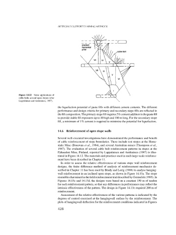
Figure 14.12 Some applications of
cable bolts around open stopes (after
Lappalainen and Antikainen, 1987).
the liquefaction potential of paste fills with different cement contents. The different
performance and design criteria for primary and secondary stope fills are reflected in
the fill composition. The primary stope fill requires 5% cement addition in the paste fill
to provide stable fill exposures up to 40 high and 100 m long. For the secondary stope
fill, a minimum of 1% cement is required to minimize the potential for liquefaction.
14.6 Reinforcement of open stope walls
Several well-executed investigations have demonstrated the performance and benefit
of cable reinforcement of stope boundaries. These include test stopes at the Home-
stake Mine (Donovan et al., 1984), and several Australian mines (Thompson et al.,
1987). The evaluation of several cable bolt reinforcement patterns in stopes at the
Pyhasalmi Mine, Finland, reported by Lappalainen and Antikainen (1987) is illus-
trated in Figure 14.12. The materials and practices used in such large-scale reinforce-
ment have been described in Chapter 11.
In order to assess the relative effectiveness of various stope wall reinforcement
designs, the finite difference method of analysis of reinforcement mechanics de-
scribed in Chapter 11 has been used by Brady and Lorig (1988) to analyse hanging-
wall reinforcement in an inclined open stope, as shown in Figure 14.13a. The stope
resembles that mined in the field reinforcement trial described by Greenelsh (1985). In
Figures 14.13c and 14.13d, the designs were based on a constant 150 m of tendon
for each reinforcement pattern, so that any differences in performance may reflect the
intrinsic effectiveness of the pattern. The design in Figure 14.13e required 200 m of
reinforcement.
Assessment of the relative effectiveness of the various patterns is indicated by the
degrees of control exercised at the hangingwall surface by the reinforcement. The
plots of hangingwall deflection for the reinforcement conditions indicated in Figures
428