
Page 450 - Rock Mechanics For Underground Mining
P. 450
LONGWALL AND CAVING MINING METHODS
rockburst than in a pillar burst due to the larger volume of rock involved. However,
in an operating stope, a local pillar or face burst may be as destructive as a large
slip on an adjacent fault. Techniques are required to identify mining layouts which
may be subject to each type of burst, and to develop preferred extraction layouts and
sequences to restrict burst frequency.
15.2.2 Rockburst controls
The concept of the ‘stress drop’ on a fault subject to frictional sliding was introduced
Figure 15.2 Shear stress drop in the in Chapter 10. It is defined by ( s − d ), the difference between the limiting static and
transition from static to dynamic con-
ditions on a fault (after Ryder, 1987). dynamic shear strengths at the prevailing normal stress, in the transition from static
to dynamic conditions on the fault. The average stress drop, e , illustrated in Figure
15.2, has been suggested to be in the range 0.1–10 MPa (Spottiswoode and McGarr,
1975). Stress drops of 5–10% of the static shear strength of a fault have been observed
in the laboratory.
Application of notions of stress drop in rockburst mechanics has been discussed by
Ryder (1987). It was proposed that the excess shear stress (ESS) on a fault, defined
by the stress drop ( e = s − d ), may be used as an indicator of the potential for
unstable slip on a fault, as it is the forcing function for the motion.
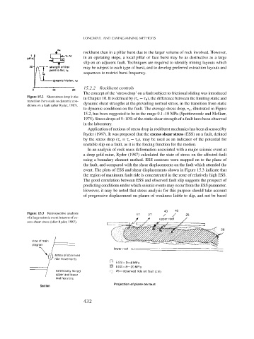
In an analysis of rock mass deformation associated with a major seismic event at
a deep gold mine, Ryder (1987) calculated the state of stress on the affected fault
using a boundary element method. ESS contours were mapped on to the plane of
the fault, and compared with the shear displacements on the fault which attended the
event. The plots of ESS and shear displacements shown in Figure 15.3 indicate that
the region of maximum fault ride is concentrated in the zone of relatively high ESS.
The good correlation between ESS and observed fault slip suggests the prospect of
predicting conditions under which seismic events may occur from the ESS parameter.
However, it may be noted that stress analysis for this purpose should take account
of progressive displacement on planes of weakness liable to slip, and not be based
Figure 15.3 Retrospective analysis
of a large seismic event in terms of ex-
cess shear stress (after Ryder, 1987).
432