
Page 582 - Rock Mechanics For Underground Mining
P. 582
MONITORING ROCK MASS PERFORMANCE
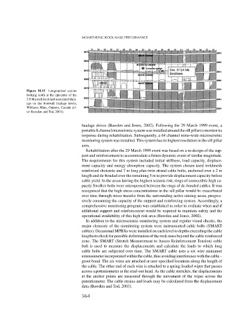
Figure 18.15 Longitudinal section
looking north at the epicentre of the
3.0 Mn rockburst and associated dam-
age on the footwall haulage levels,
Williams Mine, Ontario, Canada (af-
ter Bawden and Tod, 2003).
haulage drives (Bawden and Jones, 2002). Following the 29 March 1999 event, a
portable8channelmicroeismicsystemwasinstalledaroundthesillpillartomonitorits
response during rehabilitation. Subsequently, a 64 channel mine-wide microseismic
monitoring system was installed. This system has its highest resolution in the sill pillar
area.
Rehabilitation after the 29 March 1999 event was based on a re-design of the sup-
port and reinforcement to accommodate a future dynamic event of similar magnitude.
The requirements for this system included initial stiffness, load capacity, displace-
ment capacity and energy absorption capacity. The system chosen used weldmesh
reinforced shotcrete and 7 m long plan twin strand cable bolts, anchored over a 2 m
length and de-bonded over the remaining5mtoprovide displacement capacity before
cable yield. In the areas having the highest seismic risk, rings of connectible high ca-
pacity Swellex bolts were interspersed between the rings of de-bonded cables. It was
recognised that the high stress concentrations in the sill pillar would be exacerbated
over time through stress transfer from the surrounding active mining areas, progres-
sively consuming the capacity of the support and reinforcing system. Accordingly, a
comprehensive monitoring program was established in order to evaluate when and if
additional support and reinforcement would be required to maintain safety and the
operational availability of this high risk area (Bawden and Jones, 2002).
In addition to the microseismic monitoring system and regular visual checks, the
major elements of the monitoring system were instrumented cable bolts (SMART
cables). Occasional MPBXs were installed on each level to depths exceeding the cable
lengths to check for possible deformation of the rock mass beyond the cable reinforced
zone. The SMART (Stretch Measurement to Assess Reinforcement Tension) cable
bolt is used to measure the displacements and calculate the loads to which long
cable bolts are subjected over time. The SMART cable uses a six wire miniature
extensometerincorporatedwithinthecable,thusavoidinginterferencewiththecable–
grout bond. The six wires are attached at user-specified locations along the length of
the cable. The other end of each wire is attached to a spring-loaded wiper that passes
across a potentiometer at the read-out head. As the cable stretches, the displacements
at the anchor points are measured through the movement of the wiper across the
potentiometer. The cable strains and loads may be calculated from the displacement
data (Bawden and Tod, 2003).
564