
Page 587 - Rock Mechanics For Underground Mining
P. 587
DETERMINATION OF THE LINE OF INTERSECTION OF TWO PLANES
Figure A.1 Plotting the great circle (2) Measure off the dip direction (130 ) clockwise from the north point around the
◦
and pole to a plane on the meridional
perimeter of the net and mark this direction on the tracing paper (Figure A.1a).
projection.
Alternatively, measure 130 − 90 = 40 from the north point and mark in the
◦
◦
◦
strike line, shown dashed in Figure A.1a.
(3) Rotate the tracing about the centre pin until the dip direction lies on the east–west
diameter of the net.
(4) Count from the perimeter of the net, along the east–west diameter, the dip (50 )
◦
and trace in the great circle passing through this point (Figure A.1b).
(5) Plot the pole to the plane by counting a further 90 along the east–west diameter
◦
with the dip direction still aligned with the east–west axis (Figure A.1b). Alter-
natively, the pole may be plotted as the projection of the line 310/40 using the
construction described in section A.1.
(6) Rotate the tracing paper so that the north point is returned to its home position.
The final appearance of the stereographic projection of the great circle and pole
to the plane 130/50 is shown in Figure A.1c.
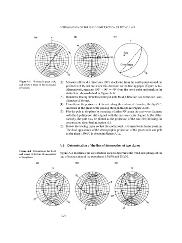
A.3 Determination of the line of intersection of two planes
Figure A.2 Determining the trend
and plunge of the line of intersection Figure A.2 illustrates the construction used to determine the trend and plunge of the
of two planes. line of intersection of the two planes 130/50 and 250/30.
569