Page 591 - Rock Mechanics For Underground Mining
P. 591

ROTATION ABOUT AN INCLINED AXIS


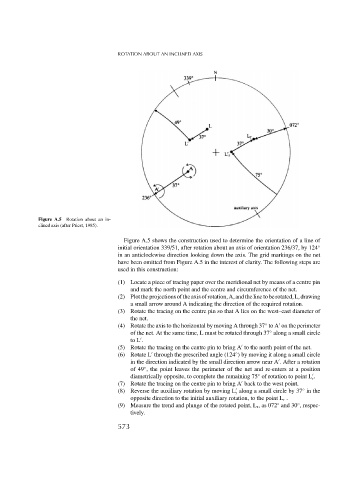
              Figure A.5 Rotation about an in-
              clined axis (after Priest, 1985).

                                          Figure A.5 shows the construction used to determine the orientation of a line of
                                        initial orientation 339/51, after rotation about an axis of orientation 236/37, by 124 ◦
                                        in an anticlockwise direction looking down the axis. The grid markings on the net
                                        have been omitted from Figure A.5 in the interest of clarity. The following steps are
                                        used in this construction:

                                        (1) Locate a piece of tracing paper over the meridional net by means of a centre pin
                                            and mark the north point and the centre and circumference of the net.
                                        (2) Plottheprojectionsoftheaxisofrotation,A,andthelinetoberotated,L,drawing
                                            a small arrow around A indicating the direction of the required rotation.
                                        (3) Rotate the tracing on the centre pin so that A lies on the west–east diameter of
                                            the net.
                                        (4) Rotate the axis to the horizontal by moving A through 37 to A on the perimeter
                                                                                         ◦

                                            of the net. At the same time, L must be rotated through 37 along a small circle
                                                                                          ◦

                                            to L .
                                        (5) Rotate the tracing on the centre pin to bring A to the north point of the net.

                                                                               ◦

                                        (6) Rotate L through the prescribed angle (124 ) by moving it along a small circle

                                            in the direction indicated by the small direction arrow near A . After a rotation
                                                 ◦
                                            of 49 , the point leaves the perimeter of the net and re-enters at a position

                                                                                      ◦
                                            diametrically opposite, to complete the remaining 75 of rotation to point L .
                                                                                                        r
                                        (7) Rotate the tracing on the centre pin to bring A back to the west point.


                                        (8) Reverse the auxiliary rotation by moving L along a small circle by 37 in the
                                                                                                     ◦
                                                                               r
                                            opposite direction to the initial auxiliary rotation, to the point L r .
                                        (9) Measure the trend and plunge of the rotated point, L r ,as072 and 30 , respec-
                                                                                                   ◦
                                                                                             ◦
                                            tively.
                                        573
   586   587   588   589   590   591   592   593   594   595   596