
Page 596 - Rock Mechanics For Underground Mining
P. 596
APPENDIX C ROCK–SUPPORT INTERACTION ANALYSIS
C.3.3 Support stiffness and maximum support pressure for ungrouted
mechanically or chemically anchored rockbolts or cables
Input data
Important items of data required in this case are obtained from the results of pull-out
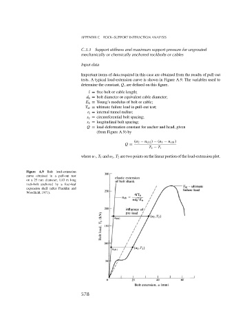
tests. A typical load-extension curve is shown in Figure A.9. The variables used to
determine the constant, Q, are defined on this figure.
l = free bolt or cable length;
d b = bolt diameter or equivalent cable diameter;
E b = Young’s modulus of bolt or cable;
T bf = ultimate failure load in pull-out test;
r i = internal tunnel radius;
s c = circumferential bolt spacing;
s = longitudinal bolt spacing;
Q = load-deformation constant for anchor and head, given
(from Figure A.9) by
(u 2 − u eb2 ) − (u 1 − u eb1 )
Q =
T 2 − T 1
where u 1 , T 1 and u 2 , T 2 are two points on the linear portion of the load-extension plot.
Figure A.9 Bolt load–extension
curve obtained in a pull-out test
on a 25 mm diameter, 1.83 m long
rock-bolt anchored by a four-leaf
expansion shell (after Franklin and
Woodfield, 1971).
578