
Page 588 - Rock Mechanics For Underground Mining
P. 588
APPENDIX A USE OF HEMISPHERICAL PROJECTION
(1) Plot the great circle and pole of the plane 130/50 on tracing paper, using the
procedure described in section A.2.
(2) With the north point on the tracing paper in its home position, mark the dip
◦
direction of the second plane (250 ).
(3) Rotate the tracing paper about the centre pin until the dip direction lies on the
east–west diameter. This is most conveniently done in this case by aligning the
dip direction (250 ) with the west (270 ) point.
◦
◦
(4) Plot the great circle and pole to the plane 250/30 using the procedure described
in section A.2, this time counting the dip (30 ) along the west–east diameter
◦
from its western end. Figure A.2a shows the appearance of the plot with the
north point returned to its home position.
(5) Rotate the tracing about the centre pin until the intersection of the two great
circles which defines the line of intersection of the two planes, lies on the west–
east diameter of the net (Figure A.2b).
◦
(6) The plunge of the line of intersection is measured as 21 by counting along the
◦
west–east axis from the 270 point to the great circle intersection (Figure A.2b).
In other problems, it may be more convenient to align the intersection point with
the east–west diameter on the eastern side of the net and count the plunge from
◦
the east or 90 point.
(7) With the tracing in this position, the poles of the two planes lie on the same great
circle (Figure A.2b). This provides an alternative means of locating the line of
intersection as the pole to the great circle passing through the poles to the two
planes.
(8) Rotate the tracing to return the north point to its home position.
(9) Draw a straight line through the centre of the net and the point of intersection of
the two great circles, to the perimeter of the net. This line defines the trend of the
◦
line of intersection, measured as 201 clockwise from the north point (Figure
A.2c).
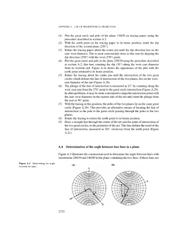
A.4 Determination of the angle between two lines in a plane
Figure A.3 illustrates the construction used to determine the angle between lines with
orientations 240/54 and 140/40 in the plane containing the two lines. If these lines are
Figure A.3 Determining the angle
between two lines.
570