
Page 589 - Rock Mechanics For Underground Mining
P. 589
DETERMINATION OF DIP DIRECTION AND TRUE DIP
the normals to two planes, then the construction may be used to determine the angle
between the two planes.
(1) Plot the projections of the two lines using the procedure described in section
A.1. These points are marked A and B in Figure A.3a.
(2) Rotate the tracing about the centre point until points A and B lie on the same
great circle of the stereonet (Figure A.3b). The dip and dip direction of the plane
which contains the two lines are measured from the stereonet as 60 and 200 ,
◦
◦
respectively.
◦
(3) The angle between the lines is found to be 64 by counting the small circle
divisions between A and B along the great circle (Figure A.3b).
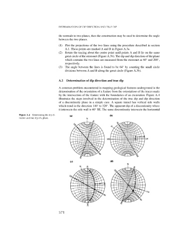
A.5 Determination of dip direction and true dip
A common problem encountered in mapping geological features underground is the
determination of the orientation of a feature from the orientations of the traces made
by the intersection of the feature with the boundaries of an excavation. Figure A.4
illustrates the steps involved in the determination of the true dip and dip direction
of a discontinuity plane in a simple case. A square tunnel has vertical side walls
◦
◦
which trend in the direction 140 to 320 . The apparent dip of a discontinuity where
it intersects the side wall is 40 SE. The same discontinuity intersects the horizontal
◦
Figure A.4 Determining the dip di-
rection and true dip of a plane.
571