
Page 98 - Rock Mechanics For Underground Mining
P. 98
ROCK MASS STRUCTURE AND CHARACTERISATION
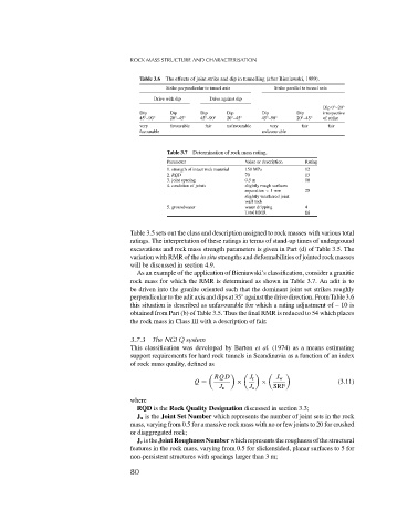
Table 3.6 The effects of joint strike and dip in tunnelling (after Bieniawski, 1989).
Strike perpendicular to tunnel axis Strike parallel to tunnel axis
Drive with dip Drive against dip
◦
Dip 0 –20 ◦
Dip Dip Dip Dip Dip Dip irrespective
45 –90 ◦ 20 –45 ◦ 45 –90 ◦ 20 –45 ◦ 45 –90 ◦ 20 –45 ◦ of strike
◦
◦
◦
◦
◦
◦
very favourable fair unfavourable very fair fair
favourable unfavourable
Table 3.7 Determination of rock mass rating.
Parameter Value or description Rating
1. strength of intact rock material 150 MPa 12
2. RQD 70 13
3. joint spacing 0.5 m 10
4. condition of joints slightly rough surfaces
separation < 1mm 25
slightly weathered joint
wall rock
5. groundwater water dripping 4
Total RMR 64
Table 3.5 sets out the class and description assigned to rock masses with various total
ratings. The interpretation of these ratings in terms of stand-up times of underground
excavations and rock mass strength parameters is given in Part (d) of Table 3.5. The
variation with RMR of the in situ strengths and deformabilities of jointed rock masses
will be discussed in section 4.9.
As an example of the application of Bieniawski’s classification, consider a granitic
rock mass for which the RMR is determined as shown in Table 3.7. An adit is to
be driven into the granite oriented such that the dominant joint set strikes roughly
perpendicular to the adit axis and dips at 35 against the drive direction. From Table 3.6
◦
this situation is described as unfavourable for which a rating adjustment of – 10 is
obtained from Part (b) of Table 3.5. Thus the final RMR is reduced to 54 which places
the rock mass in Class III with a description of fair.
3.7.3 The NGI Q system
This classification was developed by Barton et al. (1974) as a means estimating
support requirements for hard rock tunnels in Scandinavia as a function of an index
of rock mass quality, defined as
RQD J r J w
Q = × × (3.11)
J n J a SRF
where
RQD is the Rock Quality Designation discussed in section 3.3;
J n is the Joint Set Number which represents the number of joint sets in the rock
mass, varying from 0.5 for a massive rock mass with no or few joints to 20 for crushed
or diaggregated rock;
J r is the Joint Roughness Number which represents the roughness of the structural
features in the rock mass, varying from 0.5 for slickensided, planar surfaces to 5 for
non-persistent structures with spacings larger than 3 m;
80