
Page 97 - Rock Mechanics For Underground Mining
P. 97
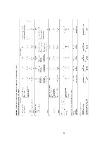
< 1  0


                           for this low range, uniaxial compression test is preferred  1–5  5–25  1  2  < 25  3  < 0.06  5  soft gouge > 5 mm thick  or  separation > 5 mm.  continuous joints  0  > 125  > 0.5  flowing  0  very unfavourable  −12  −25  −60  < 20  V  very poor rock  V  30 minutes for 1.0 m  span  < 100  < 15 ◦


                           1–2  25–50  4  25–50  8  0.06–0.2  8  slickensided surfaces  gouge < 5 mm thick  separation 1–5 mm  continuous joints  10  25–125  0.2–0.5  dripping  4  unfavourable  −10  −15  −50  40 ← 21  IV  poor rock  IV  10 hours for 2.5 m  100–200  15 ◦ –25 ◦
                         Ranges of Values      or  or                                             span


                           2–4  50–100  7  50–75  13  0.2–0.6  10  slightly rough  surfaces,  separation  < 1 mm, higly  weathered walls  20  10–25  0.1–0.2  wet  7  fair  −5  −7  −25  60 ← 41  III  fair rock  III  1 week for 5 m  span  200–300  25 ◦ –35 ◦


                    Geomechanics classification of jointed rock masses (after Bieniawski, 1989).
                           4–10  100–250  12  75–90  17  0.6–2  15  slightly rough  surfaces,  separation  < 1 mm, highly  weathered walls  25  < 10  < 0.1  damp  10  favourable  −2  −2  −5  80 ← 61  II  good rock  II  1 year for 10 m  span  300–400  35 ◦ –45 ◦


                           > 10  > 250  15  90–100  20  > 2  20  very rough  surfaces, not  continuous, no  separation,  unweathered  joint wall rock  30  none  0  completely dry  15  very favourable  0  0  0  100 ← 81  I  very good rock  I  20 years for 15 m  span  > 400  45 ◦


                      (a) Classification parameters and their ratings  Parameter  ⎧ point–load–strength  ⎪ index(MPa)  ⎪  ⎪  ⎨  ⎪ ⎪uniaxial compressive ⎪ strength (MPa) ⎩  drill core quality RQD (1%)  ⎧ inflow per 10 m tunnel ⎪ length (  min −1 )  ⎪  ⎪ ⎪ or ⎪  ⎨ joint water pressure ⎪ major principal stress  ⎪  ⎪  ⎪ ⎪or ⎩ general conditions  (b) Rating adjustment for joint orientations strike and dip orientations of joints ⎧ tunnels and micro  ⎨  ⎩ foundations  slopes (


                    Table 3.5  Strength of inftact  1  rock material  rating  2  rating  joint spacing (m)  3  rating  condition of joints  4  rating  5  groundwater  rating  Rating  Ratings  Class no.  Description  (d) Meaning of rock classes  Class no.  average stand-up time


                                                                         79