
Page 100 - Root Cause Failure Analysis
P. 100
Pumps 91
pressure are the burst pressure of the system’s components and the maximum driver
horsepower.
As a result of their ability to generate almost unlimited pressure, all positive-displace-
ment pumps’ systems must be fitted with relief valves on the downstream side of the
discharge valve. This is required to protect the pump and its discharge piping from
overpressurization. Some designs include a relief valve integral to the pump’s hous-
ing. Others use a separate valve installed in the discharge piping.
Positive-displacement pumps deliver a definite volume of liquid for each cycle of
pump operation. Therefore, the only factor, except for pipe blockage, that affects the
flow rate in an ideal positive-displacement pump is the speed at which it operates. The
flow resistance of the system in which the pump is operating does not affect the flow
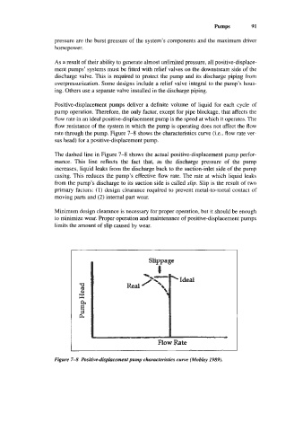
rate through the pump. Figure 7-8 shows the characteristics curve (Le., flow rate ver-
sus head) for a positive-displacement pump.
The dashed line in Figure 7-8 shows the actual positive-displacement pump perfor-
mance. This line reflects the fact that, as the discharge pressure of the pump
increases, liquid leaks from the discharge back to the suction-inlet side of the pump
casing. This reduces the pump’s effective flow rate. The rate at which liquid leaks
from the pump’s discharge to its suction side is called slip. Slip is the result of two
primary factors: (1) design clearance required to prevent metal-to-metal contact of
moving parts and (2) internal part wear.
Minimum design clearance is necessary for proper operation, but it should be enough
to minimize wear. Proper operation and maintenance of positive-displacement pumps
limits the amount of slip caused by wear.
I Flow Rate
Figure 7-8 Positive-dkplacement pump characteristics curve (Mobley 1989).