
Page 138 - Root Cause Failure Analysis
P. 138
126 Root Cause Failure Analysis
To Dlscharg~
A
BaIandngPhn
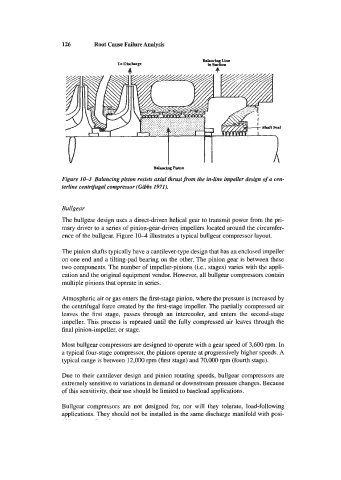
Figure 10-3 Balancingpiston resists axial thrustfrom the in-line impeller design of a cen-
terline centrifugal compressor (Gibbs 1971).
Bullgear
The bullgear design uses a direct-driven helical gear to transmit power from the pri-
mary driver to a series of pinion-gear-driven impellers located around the circumfer-
ence of the bullgear. Figure 10-4 illustrates a typical bullgear compressor layout.
The pinion shafts typically have a cantilever-type design that has an enclosed impeller
on one end and a tilting-pad bearing on the other. The pinion gear is between these
two components. The number of impeller-pinions (Le., stages) varies with the appli-
cation and the original equipment vendor. However, all bullgear compressors contain
multiple pinions that operate in series.
Atmospheric air or gas enters the first-stage pinion, where the pressure is increased by
the centrifugal force created by the first-stage impeller. The partially compressed air
leaves the first stage, passes through an intercooler, and enters the second-stage
impeller. This process is repeated until the fully compressed air leaves through the
final pinion-impeller, or stage.
Most bullgear compressors are designed to operate with a gear speed of 3,600 rpm. In
a typical four-stage compressor, the pinions operate at progressively higher speeds. A
typical range is between 12,000 rpm (first stage) and 70,000 rpm (fourth stage).
Due to their cantilever design and pinion rotating speeds, bullgear compressors are
extremely sensitive to variations in demand or downstream pressure changes. Because
of this sensitivity, their use should be limited to baseload applications.
Bullgear compressors are not designed for, nor will they tolerate, load-following
applications. They should not be installed in the same discharge manifold with posi-