
Page 142 - Root Cause Failure Analysis
P. 142
130 Root Cause Failure Analysis
Rotary
The rotary compressor is adaptable to direct drive by the use of induction motors or
multicylinder gasoline or diesel engines. These compressors are compact, relatively
inexpensive, and require a minimum of operating attention and maintenance. They
occupy a fraction of the space and weight of a reciprocating machine having equiva-
lent capacity.
Rotary compressors are classified into three general groups: sliding vane, helical lobe,
and liquid-seal ring.
Sliding Vane
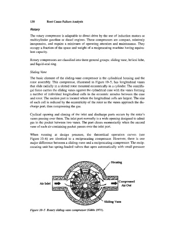
The basic element of the sliding-vane compressor is the cylindrical housing and the
rotor assembly. This compressor, illustrated in Figure 10-5, has longitudinal vanes
that slide radially in a slotted rotor mounted eccentrically in a cylinder. The centrifu-
gal force carries the sliding vanes against the cylindrical case with the vanes forming
a number of individual longitudinal cells in the eccentric annulus between the case
and rotor. The suction port is located where the longitudinal cells are largest. The size
of each cell is reduced by the eccentricity of the rotor as the vanes approach the dis-
charge port, thus compressing the gas.
Cyclical opening and closing of the inlet and discharge ports occurs by the rotor’s
vanes passing over them. The inlet port normally is a wide opening designed to admit
gas in the pocket between two vanes. The port closes momentarily when the second
vane of each air-containing pocket passes over the inlet port.
When running at design pressure, the theoretical operation curves (see
Figure 10-6) are identical to a reciprocating compressor. However, there is one
major difference between a sliding-vane and a reciprocating compressor. The recip-
rocating unit has spring-loaded valves that open automatically with small pressure
Figure 1&5 Rotary sliding-vane compressor (Gibbs 1971).