
Page 143 - Root Cause Failure Analysis
P. 143
Compressors 131
OPERATION AT
DESIGN PRESSURE
OPERATION A6OVE
OESIGN PRESSURE
LA
i I_....___I 1 __ .
VOLUME
.,. -7-"- T . . . .--
-IC.N P*e:ssume
OPEmariou srrow
DESIGN PRESSURE
VOLUME
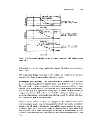
Figure IM Theoretical operation curves for rotary compressors with built-in porting
(Gibbs 1971).
differentials between the outside and inside cylinder. The sliding-vane compressor
has no valves.
The fundamental design considerations of a sliding-vane compressor are the rotor
assembly, the cylinder housing, and the lubrication system.
Housing and Rotor Assembly Cast iron is the standard material used to construct
the cylindrical housing, but other materials may be used if corrosive conditions exist.
The rotor usually is a continuous piece of steel that includes the shaft and is made
from bar stock. Special materials can be selected for corrosive applications. Occasion-
ally, the rotor may be a separate iron casting keyed to a shaft. On most standard air
compressors, the rotor-shaft seals are semi-metallic packing in a stuffing box. Com-
mercial mechanical rotary seals can be supplied when needed. Cylindrical roller bear-
ings generally are used in these assemblies.
Vanes usually are asbestos or cotton cloth impregnated with a phenolic resin. Bronze
or aluminum also may be used for vane construction. Each vane fits into a milled slot
extending the full length of the rotor and slides radially in and out of this slot once per
revolution. Vanes are the part in the compressor most in need of maintenance. Each
rotor has from 8 to 20 vanes, depending on its diameter. A greater number of vanes
increases compartmentalization, which reduces the pressure differential across each
vane.