
Page 150 - Root Cause Failure Analysis
P. 150
138 Root Cause Failure Analysis
Inlet and Discharge Valves Compressor valves are placed in each cylinder to per-
mit one-way flow of gas, either into or out of the cylinder. One or more valve(s) is
needed for inlet and discharge in each compression chamber.
Each valve opens and closes once for each revolution of the crankshaft. The valves in
a compressor operating at 700 rpm for 8 hours per day and 250 days per year will
have cycled (i-e., opened and closed) 42,000 times per hour, 336,000 times per day, or
84 million times in a year. The valves have less than '/lo of a second to open, let the
gas pass through, and close.
They must cycle with a minimum of resistance for minimum power consumption.
However, the valves must have minimal clearance to prevent excessive expansion and
reduced volumetric efficiency. They must be tight under extreme pressure and temper-
ature conditions. Finally, the valves must be durable under many kinds of abuse.
Four basic valve designs are used in these compressors: finger, channel, leaf, and
annular ring. Each class may contain variations in design, depending on operating
speed and size of valve required.
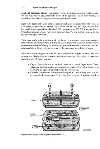
Finger. Figure 10-9 is an exploded view of a typical finger valve. These
valves are used for smaller, air-cooled compressors. One end of the finger is
fixed, and the opposite end lifts when the valve opens.
Channel. The channel valve shown in Figure 10-10 is widely used in mid-
to large-sized compressors. This valve uses a series of separate stainless
HEAD
Gh
CYLINDER
Figure 10-9 Finger valve confguration (Gibbs 1971).