
Page 151 - Root Cause Failure Analysis
P. 151
Compressors 139
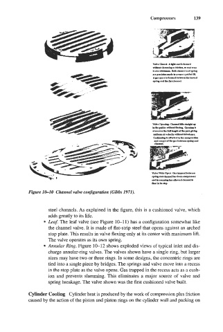
Figure 10-10 Channel valve configuration (Gibbs 1971).
steel channels. As explained in the figure, this is a cushioned valve, which
adds greatly to its life.
Leaf. The leaf valve (see Figure 10-11) has a configuration somewhat like
the channel valve. It is made of flat-strip steel that opens against an arched
stop plate. This results in valve flexing only at its center with maximum lift.
The valve operates as its own spring.
Annular Ring. Figure 10-12 shows exploded views of typical inlet and dis-
charge annular-ring valves. The valves shown have a single ring, but larger
sizes may have two or three rings. In some designs, the concentric rings are
tied into a single piece by bridges. The springs and valve move into a recess
in the stop plate as the valve opens. Gas trapped in the recess acts as a cush-
ion and prevents slamming. This eliminates a major source of valve and
spring breakage. The valve shown was the first cushioned valve built.
Cylinder Cooling Cylinder heat is produced by the work of compression plus friction
caused by the action of the piston and piston rings on the cylinder wall and packing on