
Page 102 - Rotating Machinery Pratical Solutions to Unbalance and Misalignment
P. 102
Rotating Machinery: Practical Solutions
The first step is to lay out a circle whose radius is equal to the
amplitude of the original vibration. Remember, any convenient
scale can be used, but be sure to allow for the additional circles
which will be drawn with their centers located around the original
circle’s circumference. As a minimum, allow 4 times the original
amplitude to be the minimum layout. That is, if the original am-
plitude was 46 mils, a minimum of 4 × 46 or 184 divisions should
be available. Since the selected graph paper has 100 divisions, a
scale of 5 to 1 was chosen. Thus, the required minimum would be
(46/5)*4 or 36.8 divisions which will fit on the selected graph
paper. Note: a scale of 2 to 1 could be used in this example. Using
a scale of 5 mils per division, the circle would have a radius of 46/
5 or 9.2 divisions.
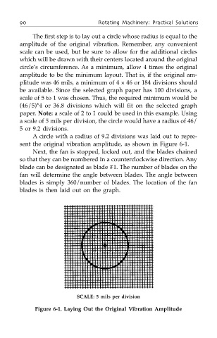
A circle with a radius of 9.2 divisions was laid out to repre-
sent the original vibration amplitude, as shown in Figure 6-1.
Next, the fan is stopped, locked out, and the blades chained
so that they can be numbered in a counterclockwise direction. Any
blade can be designated as blade #1. The number of blades on the
fan will determine the angle between blades. The angle between
blades is simply 360/number of blades. The location of the fan
blades is then laid out on the graph.
SCALE: 5 mils per division
Figure 6-1. Laying Out the Original Vibration Amplitude