
Page 103 - Rotating Machinery Pratical Solutions to Unbalance and Misalignment
P. 103
A Single Plane Balancing Technique
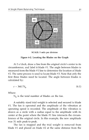
SCALE: 5 mils per division
Figure 6-2. Locating the Blades on the Graph
At 3 o’clock, draw a line from the original circle’s center to its
circumference, and label it blade #1. The angle between blades is
measured from the blade #1 line to determine the location of blade
#2. The same process is used to locate blade #3. Note that only the
first three blades need be located. The angle between blades is
calculated by:
e = 360/N (6.1)
b
Where:
N is the total number of blades on the fan.
b
A suitably sized trial weight is selected and secured to blade
#1. The fan is operated and the amplitude of the vibration at
operating speed is recorded. The amplitude of this vibration is
drawn as a circle with a radius equal to the amplitude with its
center at the point where the blade #1 line intersects the circum-
ference of the original circle. In this example, the new amplitude
was 31 mils peak-to-peak.
The fan is stopped and the trial weight is removed from
blade #1 and placed on blade #2 at the same distance from the