
Page 106 - Rotating Machinery Pratical Solutions to Unbalance and Misalignment
P. 106
Rotating Machinery: Practical Solutions
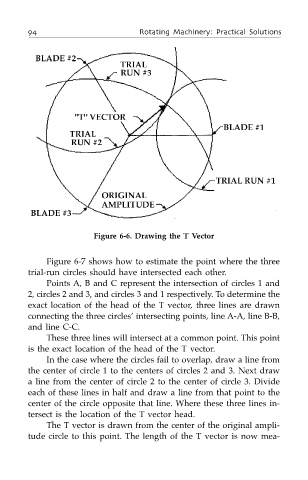
Figure 6-6. Drawing the T Vector
Figure 6-7 shows how to estimate the point where the three
trial-run circles should have intersected each other.
Points A, B and C represent the intersection of circles 1 and
2, circles 2 and 3, and circles 3 and 1 respectively. To determine the
exact location of the head of the T vector, three lines are drawn
connecting the three circles’ intersecting points, line A-A, line B-B,
and line C-C.
These three lines will intersect at a common point. This point
is the exact location of the head of the T vector.
In the case where the circles fail to overlap, draw a line from
the center of circle 1 to the centers of circles 2 and 3. Next draw
a line from the center of circle 2 to the center of circle 3. Divide
each of these lines in half and draw a line from that point to the
center of the circle opposite that line. Where these three lines in-
tersect is the location of the T vector head.
The T vector is drawn from the center of the original ampli-
tude circle to this point. The length of the T vector is now mea-