
Page 116 - Rotating Machinery Pratical Solutions to Unbalance and Misalignment
P. 116
Rotating Machinery: Practical Solutions
would be 210 degrees from the top, etc.
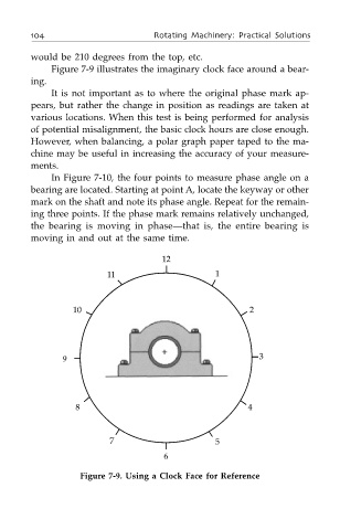
Figure 7-9 illustrates the imaginary clock face around a bear-
ing.
It is not important as to where the original phase mark ap-
pears, but rather the change in position as readings are taken at
various locations. When this test is being performed for analysis
of potential misalignment, the basic clock hours are close enough.
However, when balancing, a polar graph paper taped to the ma-
chine may be useful in increasing the accuracy of your measure-
ments.
In Figure 7-10, the four points to measure phase angle on a
bearing are located. Starting at point A, locate the keyway or other
mark on the shaft and note its phase angle. Repeat for the remain-
ing three points. If the phase mark remains relatively unchanged,
the bearing is moving in phase—that is, the entire bearing is
moving in and out at the same time.
12
11 1
10 2
9 3
8 4
7 5
6
Figure 7-9. Using a Clock Face for Reference