
Page 117 - Rotating Machinery Pratical Solutions to Unbalance and Misalignment
P. 117
Misalignment of Machine Shafts
A
D + B
C
Figure 7-10. Locating Four Reference Points
The next step is to measure the bearing across the coupling.
Often, this will require the pickup to be placed in the opposite
direction. If the pickup is reversed, the new phase readings must
be adjusted by 180 degrees.
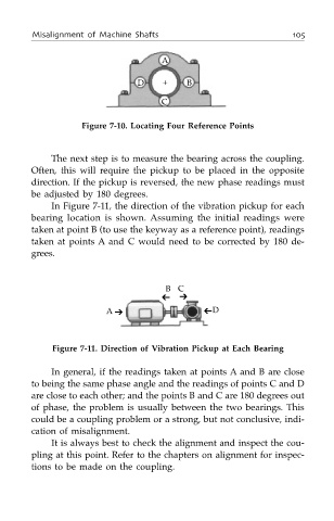
In Figure 7-11, the direction of the vibration pickup for each
bearing location is shown. Assuming the initial readings were
taken at point B (to use the keyway as a reference point), readings
taken at points A and C would need to be corrected by 180 de-
grees.
B C
➔
➔
A ➔ ➔
D
Figure 7-11. Direction of Vibration Pickup at Each Bearing
In general, if the readings taken at points A and B are close
to being the same phase angle and the readings of points C and D
are close to each other; and the points B and C are 180 degrees out
of phase, the problem is usually between the two bearings. This
could be a coupling problem or a strong, but not conclusive, indi-
cation of misalignment.
It is always best to check the alignment and inspect the cou-
pling at this point. Refer to the chapters on alignment for inspec-
tions to be made on the coupling.