
Page 140 - Rotating Machinery Pratical Solutions to Unbalance and Misalignment
P. 140
Rotating Machinery: Practical Solutions
other. This line is labeled the final alignment line. Note that if
thermal growth is not to be considered, this line represents the
present location of the stationary machine’s shaft centerline.
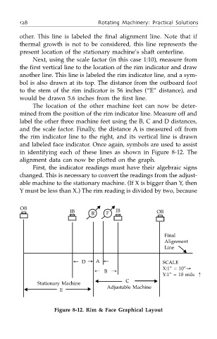
Next, using the scale factor (in this case 1:10), measure from
the first vertical line to the location of the rim indicator and draw
another line. This line is labeled the rim indicator line, and a sym-
bol is also drawn at its top. The distance from the outboard foot
to the stem of the rim indicator is 56 inches (“E” distance), and
would be drawn 5.6 inches from the first line.
The location of the other machine feet can now be deter-
mined from the position of the rim indicator line. Measure off and
label the other three machine feet using the B, C and D distances,
and the scale factor. Finally, the distance A is measured off from
the rim indicator line to the right, and its vertical line is drawn
and labeled face indicator. Once again, symbols are used to assist
in identifying each of these lines as shown in Figure 8-12. The
alignment data can now be plotted on the graph.
First, the indicator readings must have their algebraic signs
changed. This is necessary to convert the readings from the adjust-
able machine to the stationary machine. (If X is bigger than Y, then
Y must be less than X.) The rim reading is divided by two, because
OB ▼ ▼
IB IB OB
R F
Final
Alignment
Line
▼
← D → A ← SCALE
X:1” = 10”→
← B →
Y:1” = 10 mils ↑
▲ C ▼
Stationary Machine
▲ E ▼ Adjustable Machine
Figure 8-12. Rim & Face Graphical Layout