
Page 135 - Rotating Machinery Pratical Solutions to Unbalance and Misalignment
P. 135
Advanced Machine Alignment
A
A/2
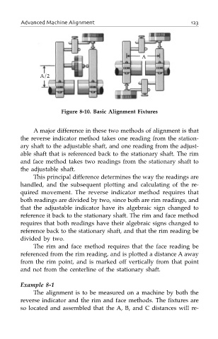
Figure 8-10. Basic Alignment Fixtures
A major difference in these two methods of alignment is that
the reverse indicator method takes one reading from the station-
ary shaft to the adjustable shaft, and one reading from the adjust-
able shaft that is referenced back to the stationary shaft. The rim
and face method takes two readings from the stationary shaft to
the adjustable shaft.
This principal difference determines the way the readings are
handled, and the subsequent plotting and calculating of the re-
quired movement. The reverse indicator method requires that
both readings are divided by two, since both are rim readings, and
that the adjustable indicator have its algebraic sign changed to
reference it back to the stationary shaft. The rim and face method
requires that both readings have their algebraic signs changed to
reference back to the stationary shaft, and that the rim reading be
divided by two.
The rim and face method requires that the face reading be
referenced from the rim reading, and is plotted a distance A away
from the rim point, and is marked off vertically from that point
and not from the centerline of the stationary shaft.
Example 8-1
The alignment is to be measured on a machine by both the
reverse indicator and the rim and face methods. The fixtures are
so located and assembled that the A, B, and C distances will re-