
Page 133 - Rotating Machinery Pratical Solutions to Unbalance and Misalignment
P. 133
Advanced Machine Alignment
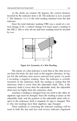
As the shafts are rotated 180 degrees, the vertical distance
traveled by the indicator stem is 2b. The indicator is now at point
1. The distance 1 to 2 is the total reading obtained from the dial
indicator.
Since the total indicator reading (TIR) was a result of a ver-
tical change of 2b, a vertical change of b must equal a reading of
the TIR/2. This is why all rim and bore readings must be divided
by two.
0
b
2b C L 2
TIR
b
1
A
Figure 8-8. Geometry of a Rim Reading
The nature of a dial indicator is such that as the stem moves
out from the body, the dial reads in the negative direction. In Fig-
ure 8-8, the indicator stem moves outward from point 1 to point
2 recording a negative reading. Since the indicator is actually
mounted on the stationary shaft, the reading is stating that the
stationary shaft is lower than the adjustable shaft. Thus, if the
stationary shaft is lower than the adjustable shaft, the adjustable
shaft must be higher than the stationary shaft.
Anytime a reading is changed from one shaft to the other, its
algebraic sign must be changed. Since the reading is taken on the
adjustable shaft, and the position of the adjustable shaft with re-
spect to the stationary shaft is required, its sign is changed. This
is why rim readings have their algebraic sign changed.
These methods of correcting the indicator readings will be
used in both the rim and face and reverse indicator alignment