
Page 131 - Rotating Machinery Pratical Solutions to Unbalance and Misalignment
P. 131
Advanced Machine Alignment
Generally, these distances should be measured to the nearest 1/4
of an inch. These distances are measured from the center of the
stem of the rim indicator to the center of the hold-down bolt.
A carpenter’s square is useful in transferring these measure-
ments to the machine centerline, where the measurements are
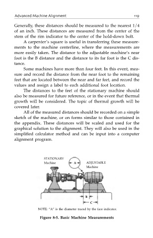
more easily taken. The distance to the adjustable machine’s near
foot is the B distance and the distance to its far foot is the C dis-
tance.
Some machines have more than four feet. In this event, mea-
sure and record the distance from the near foot to the remaining
feet that are located between the near and far feet, and record the
values and assign a label to each additional foot location.
The distances to the feet of the stationary machine should
also be measured for future reference, or in the event that thermal
growth will be considered. The topic of thermal growth will be
covered later.
All of the measured distances should be recorded on a simple
sketch of the machine, or on forms similar to those contained in
the appendix. These distances will be scaled and used for the
graphical solution to the alignment. They will also be used in the
simplified calculator method and can be input into a computer
alignment program.
STATIONARY
Machine A ADJUSTABLE
Machine
B
C
NOTE: “A” is the diameter traced by the face indicator.
Figure 8-5. Basic Machine Measurements