
Page 132 - Rotating Machinery Pratical Solutions to Unbalance and Misalignment
P. 132
Rotating Machinery: Practical Solutions
ABOUT INDICATOR READINGS
Since two points determine a straight line, the objective in
any alignment process is to locate two points on the centerline of
the adjustable machine, to determine its relative position. Once
these two points are located, with respect to the stationary ma-
chine centerline, the required movement to align the two shafts is
easily determined.
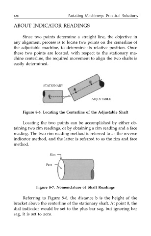
STATIONARY
ADJUSTABLE
Figure 8-6. Locating the Centerline of the Adjustable Shaft
Locating the two points can be accomplished by either ob-
taining two rim readings, or by obtaining a rim reading and a face
reading. The two rim reading method is referred to as the reverse
indicator method, and the latter is referred to as the rim and face
method.
Rim
Face
Figure 8-7. Nomenclature of Shaft Readings
Referring to Figure 8-8, the distance b is the height of the
bracket above the centerline of the stationary shaft. At point 0, the
dial indicator would be set to the plus bar sag, but ignoring bar
sag, it is set to zero.