
Page 134 - Rotating Machinery Pratical Solutions to Unbalance and Misalignment
P. 134
Rotating Machinery: Practical Solutions
processes. They are discussed in more detail later in this and the
following chapters.
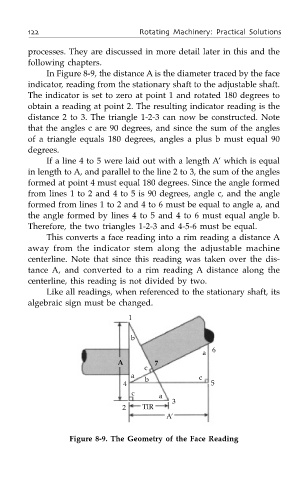
In Figure 8-9, the distance A is the diameter traced by the face
indicator, reading from the stationary shaft to the adjustable shaft.
The indicator is set to zero at point 1 and rotated 180 degrees to
obtain a reading at point 2. The resulting indicator reading is the
distance 2 to 3. The triangle 1-2-3 can now be constructed. Note
that the angles c are 90 degrees, and since the sum of the angles
of a triangle equals 180 degrees, angles a plus b must equal 90
degrees.
If a line 4 to 5 were laid out with a length A’ which is equal
in length to A, and parallel to the line 2 to 3, the sum of the angles
formed at point 4 must equal 180 degrees. Since the angle formed
from lines 1 to 2 and 4 to 5 is 90 degrees, angle c, and the angle
formed from lines 1 to 2 and 4 to 6 must be equal to angle a, and
the angle formed by lines 4 to 5 and 4 to 6 must equal angle b.
Therefore, the two triangles 1-2-3 and 4-5-6 must be equal.
This converts a face reading into a rim reading a distance A
away from the indicator stem along the adjustable machine
centerline. Note that since this reading was taken over the dis-
tance A, and converted to a rim reading A distance along the
centerline, this reading is not divided by two.
Like all readings, when referenced to the stationary shaft, its
algebraic sign must be changed.
1
b
a 6
A 7
c
a b c
4 5
c a
3
2 TIR
A’
Figure 8-9. The Geometry of the Face Reading