
Page 142 - Rotating Machinery Pratical Solutions to Unbalance and Misalignment
P. 142
Rotating Machinery: Practical Solutions
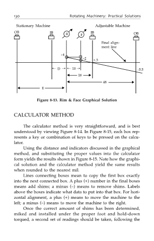
Stationary Machine Adjustable Machine
▼ ▼
OB IB R F IB OB
Final align-
ment line
+4
–2
+.5 ▼
← D → ← 10 → –5.5
▲ 18 ▼
▲ 48 ▼
▲ E ▼
Figure 8-13. Rim & Face Graphical Solution
CALCULATOR METHOD
The calculator method is very straightforward, and is best
understood by viewing Figure 8-14. In Figure 8-15, each box rep-
resents a key or combination of keys to be pressed on the calcu-
lator.
Using the distance and indicators discussed in the graphical
method, and substituting the proper values into the calculator
form yields the results shown in Figure 8-15. Note how the graphi-
cal solution and the calculator method yield the same results
when rounded to the nearest mil.
Lines connecting boxes mean to copy the first box exactly
into the next connected box. A plus (+) number in the final boxes
means add shims; a minus (–) means to remove shims. Labels
above the boxes indicate what data to put into that box. For hori-
zontal alignment, a plus (+) means to move the machine to the
left; a minus (–) means to move the machine to the right.
Once the correct amount of shims has been determined,
miked and installed under the proper foot and hold-down
torqued, a second set of readings should be taken, following the