
Page 158 - Rotating Machinery Pratical Solutions to Unbalance and Misalignment
P. 158
Rotating Machinery: Practical Solutions
Figure 8-24. Vertical Pump
3 4
2 1
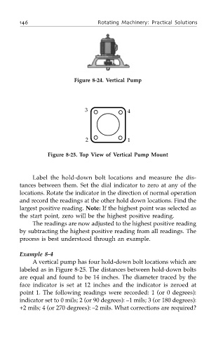
Figure 8-25. Top View of Vertical Pump Mount
Label the hold-down bolt locations and measure the dis-
tances between them. Set the dial indicator to zero at any of the
locations. Rotate the indicator in the direction of normal operation
and record the readings at the other hold down locations. Find the
largest positive reading. Note: If the highest point was selected as
the start point, zero will be the highest positive reading.
The readings are now adjusted to the highest positive reading
by subtracting the highest positive reading from all readings. The
process is best understood through an example.
Example 8-4
A vertical pump has four hold-down bolt locations which are
labeled as in Figure 8-25. The distances between hold-down bolts
are equal and found to be 14 inches. The diameter traced by the
face indicator is set at 12 inches and the indicator is zeroed at
point 1. The following readings were recorded: 1 (or 0 degrees):
indicator set to 0 mils; 2 (or 90 degrees): –1 mils; 3 (or 180 degrees):
+2 mils; 4 (or 270 degrees): –2 mils. What corrections are required?