
Page 160 - Rotating Machinery Pratical Solutions to Unbalance and Misalignment
P. 160
Rotating Machinery: Practical Solutions
Since the rim readings are all in the horizontal plane, no
compensation for bar sag is required. Zero the indicator on one
surface, such as the 1-2 side and take a reading on the opposite
side, 180 degrees away. Set the dial indicator to 1/2 its reading
and move the motor until the indicator reads zero. Repeat this
process for the side 90 degrees from the initial side, the 2-3 side.
Check the final alignment by repeating the readings to assure
the motor is centered over the pump.
THE CATENARY
Some long shafts may exhibit deflection due to their own
weight, or in combination with the weight of a mounted compo-
nent that can affect the alignment process. Perhaps the best way to
demonstrate the potential effect is through examples.
Example 8-5
A large roller is made of steel and is 6 inches in diameter. It
is supported by two bearings that are 12 feet apart. How much
will the center of the shaft sag? How much angular deflection will
be present at the end of the shaft?
Step 1. Steel weighs approximately 480 pounds per cubic foot, so
the weight of the portion of the shaft between the bearings is its
volume times the density W = V × d or W = L × A × d = (12 × π
2
× (.5) /4) × 480 or approximately 1,131 pounds.
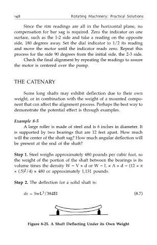
Step 2. The deflection for a solid shaft is:
3
dx = 5wL /384EI (8.7)
Figure 8-25. A Shaft Deflecting Under its Own Weight