
Page 159 - Rotating Machinery Pratical Solutions to Unbalance and Misalignment
P. 159
Advanced Machine Alignment
Step 1. The readings are now adjusted by selecting the largest
positive reading as zero, and subtracting it from all readings, as
follows: 1 (or 0 degrees): 0 mils – 2 mils = –2 mils; 2 (or 90 de-
grees): –1 mils – 2 mils = –3 mils; 3 (or 180 degrees): +2 mils – 2
mils = 0 mils; 4 (or 270 degrees): –2 mils – 2 mils = –4 mils.
As seen from the above, point 3 was the highest hold-down lo-
cation and the others will be adjusted to the same plane as point 3.
Step 2. Next, the slope is calculated. That is the change over the
diameter A traced by the face indicator. This is used to correct the
readings back to the hold-down locations.
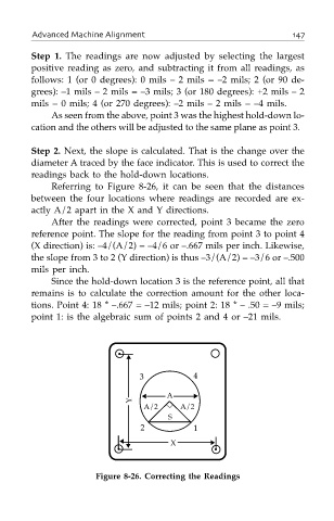
Referring to Figure 8-26, it can be seen that the distances
between the four locations where readings are recorded are ex-
actly A/2 apart in the X and Y directions.
After the readings were corrected, point 3 became the zero
reference point. The slope for the reading from point 3 to point 4
(X direction) is: –4/(A/2) = –4/6 or –.667 mils per inch. Likewise,
the slope from 3 to 2 (Y direction) is thus –3/(A/2) = –3/6 or –.500
mils per inch.
Since the hold-down location 3 is the reference point, all that
remains is to calculate the correction amount for the other loca-
tions. Point 4: 18 * –.667 = –12 mils; point 2: 18 * – .50 = –9 mils;
point 1: is the algebraic sum of points 2 and 4 or –21 mils.
•
▲
3 4
Y ▲ A ▼
A/2 A/2
S
2 1
▲ X ▼
• ▼ •
Figure 8-26. Correcting the Readings