
Page 156 - Rotating Machinery Pratical Solutions to Unbalance and Misalignment
P. 156
Rotating Machinery: Practical Solutions
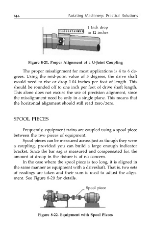
1 Inch drop
in 12 inches
Figure 8-21. Proper Alignment of a U-Joint Coupling
The proper misalignment for most applications is 4 to 6 de-
grees. Using the mid-point value of 5 degrees, the drive shaft
would need to rise or drop 1.04 inches per foot of length. This
should be rounded off to one inch per foot of drive shaft length.
This alone does not excuse the use of precision alignment, since
the misalignment need be only in a single plane. This means that
the horizontal alignment should still read zero/zero.
SPOOL PIECES
Frequently, equipment trains are coupled using a spool piece
between the two pieces of equipment.
Spool pieces can be measured across just as though they were
a coupling, provided you can build a large enough indicator
bracket. Since the bar sag is measured and compensated for, the
amount of droop in the fixture is of no concern.
In the case where the spool piece is too long, it is aligned in
the same manner as equipment with a driveshaft. That is, two sets
of readings are taken and their sum is used to adjust the align-
ment. See Figure 8-20 for details.
Spool piece
Figure 8-22. Equipment with Spool Pieces