
Page 151 - Rotating Machinery Pratical Solutions to Unbalance and Misalignment
P. 151
Advanced Machine Alignment
R ▲ F ▲
OB IB IB OB
Cold align-
ment line
• •
▼
•
–2
–7
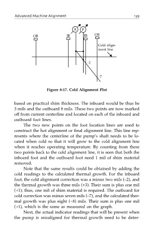
Figure 8-17. Cold Alignment Plot
based on practical shim thickness. The inboard would be thus be
3 mils and the outboard 8 mils. These two points are now marked
off from current centerline and located on each of the inboard and
outboard foot lines.
The two new points on the foot location lines are used to
construct the hot alignment or final alignment line. This line rep-
resents where the centerline of the pump’s shaft needs to be lo-
cated when cold so that it will grow to the cold alignment line
when it reaches operating temperature. By counting from these
two points back to the cold alignment line, it is seen that both the
inboard foot and the outboard foot need 1 mil of shim material
removed.
Note that the same results could be obtained by adding the
cold readings to the calculated thermal growth. For the inboard
foot, the cold alignment correction was a minus two mils (–2), and
the thermal growth was three mils (+3). Their sum is plus one mil
(+1); thus, one mil of shim material is required. The outboard for
cold correction was minus seven mils (–7), and the calculated ther-
mal growth was plus eight (+8) mils. Their sum is plus one mil
(+1), which is the same as measured on the graph.
Next, the actual indicator readings that will be present when
the pump is misaligned for thermal growth need to be deter-