
Page 164 - Rotating Machinery Pratical Solutions to Unbalance and Misalignment
P. 164
Rotating Machinery: Practical Solutions
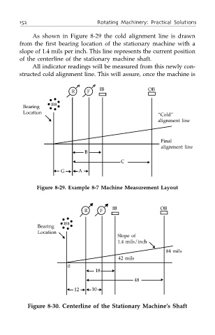
As shown in Figure 8-29 the cold alignment line is drawn
from the first bearing location of the stationary machine with a
slope of 1.4 mils per inch. This line represents the current position
of the centerline of the stationary machine shaft.
All indicator readings will be measured from this newly con-
structed cold alignment line. This will assure, once the machine is
IB OB
R F
IBB
Bearing
Location
“Cold”
▼ alignment line
Final
alignment line
▲ B ▼
▲ C ▼
▲ G ▼
▲
A ▲
Figure 8-29. Example 8-7 Machine Measurement Layout
▲
▲
IB OB
R F
IBB
Bearing
Location
▼ Slope of
1.4 mils/inch
▼
84 mils
42 mils
0
▲ 18 ▼
▲ 48 ▼
▲ 12 ▼ ▲ 10 ▲
Figure 8-30. Centerline of the Stationary Machine’s Shaft